Saturday, 14 April 2012

Project Construction

Starting from week 7 to week 10, we are working on constructing our project. Following are the tasks that we have done during the constructing progress.


1. Sand paper the PCB with abrasive paper (P400)


2. Prepare the OHP with the circuit printed on it.

3. Place the ready OHP onto the PCB.

4. Ironing the PCB with the OHP on it.

5. Wait until the ironed PCB has cool down. Then take the OHP off from the PCB slowly.

6. The ready PCB with circuit on it
7. Prepare the Ferrous acid and soak the ready PCB in it.
8. Soak the PCB for 10-15 minutes to remove the unwanted copper so that only the circuit will remain on the PCB.

9. Etching the PCB using sand paper.

10. The ready PCB

11. The process of assembling components on the PCB. 


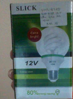
Since we could not find any electronic or electrical store that selling the 12V fluorescent lamp, we replaced  them with this bulb. 
We could not find the battery charger as specified on the magazine which is MB-3526 12V 1A in the marker. So we use the Autobike Battery Charger to charge the SLA battery so that the battery can be used to run a test on our project. 

The controller was connected to the battery

We run a test on our project.
Problem 
We have run a test to see whether the circuit of the controller for the emergency light is working or not. The circuit seems to be working properly. The only problem we have now is we do not know how we can find the right charger. The charger for this circuit are supposed to be  MB-3526 Battery Charger 12V 1A. We went to many electronic store and ask the person in charge there for this type of charger but they don't have SLA battery charger 12V with 1A. What they have is 12V 2A. 

Conclusion.
The process of assembling the components is succeed. But we must find the right charger for our project or we have to do some add the value of the resistor near the main power to prevent the Mains Power LED indicator from burning due to over current passing through it

Manage to Design The PCB

The Schematic


Above are the Schematic Figure for our project. Previously, we could not design the PCB due to there are no STP16NF06 in the library. After meeting with Sir Azman bin Ghani, we replace  STP16NF06 with LM7805 because it has a similar pattern. This is only for designing the PCB. 


Above are the PCB figure


Conclusion

The designing of the PCB for our project is succeeded.

Thursday, 29 March 2012

PN100 & MCR100 & BC639 Datasheet

PN100/PN100A/MMBT100/MMBT100A

NPN General Purpose Amplifier

• This device is designed for general purpose amplifier applications at collector currents to 300mA.


MCR100 Series


Sensitive Gate
Silicon Controlled Rectifiers
Reverse Blocking Thyristors

PNPN devices designed for high volume, line-powered consumer applications such as relay and lamp drivers, small motor controls, gate drivers for larger thyristors, and sensing and detection circuits. Supplied in an inexpensive plastic TO-226AA package which is readily adaptable for use in automatic insertion equipment.

Features:
• Sensitive Gate Allows Triggering by Microcontrollers and Other
  Logic Circuits
• Blocking Voltage to 600 V
• On−State Current Rating of 0.8 Amperes RMS at 80°C
• High Surge Current Capability − 10 A
• Minimum and Maximum Values of IGT, VGT and IH Specified
  for Ease of Design
• Immunity to dV/dt − 20 V/ sec Minimum at 110°C
• Glass-Passivated Surface for Reliability and Uniformity


BC639

NPN Silicon AF Transistors 


● High current gain
● High collector current
● Low collector-emitter saturation voltage
● Complementary types: BC 636, BC 638, BC 640 (PNP)


Buying PN100-Problem encountered

Could not find component : PN100


Above are the picture for the PN 100. This device is designed for general purpose amplifier applications at collector currents to 300 mA. This transistor are working together with the 555 timer to detect the mains fails and also act as the trigger for the 555 timer which is also IC1.We could not find the transistor. There are several number type of transistor suggested by the electronic dealer which is MCR100, BC639 and C9013. We have to do some research before proceeding.


Project Circuit Diagram


Figure above are the circuit diagram for the project. The transistor PN100 was labeled Q1,Q2 and Q3.

Designing PCB


Trying to design the PCB by using software such as DipTrace and Proteus but failed. There are no STP16NF06 found in the library. Basically, the function of the STP16NF06 is as a switch. Whenever it in OFF state, the emergency light will also in OFF state. 


Problem encountered


Unable to locate this components in the software's library.

  •  STP16NF06


Wednesday, 22 February 2012

Buying Other Components


  • LED
  • Copper Spade Lug
  • Cable Lug
  • Battery Charger 5Ah


Encountered Problem

Not able to find some kits.

  • Aluminium sheet
  • TO 220 Thermal washer or insulation kit
  • Vented instruments case
  • The power Tech 12V 1A SLA battery charger

Friday, 17 February 2012

FYP Project- Emergency 12V Lighting Controller

Buying Components


14, Jalan Landak, Off Jalan Pasar, Pudu, 55100 Kuala Lumpur.
Tel: 03 9221 8059 (Hunting lines), 9222 6703 Fax:03-92229018


List of Components


1.  12v 7Ah battery
2.  PCB 100 x 230
3.  TO 220 heatsink
4.  LM555
5.  CS 9013
6.  D16NF06
7.  1N4741 11v 1w Zener Diode
8.  1N5822 40V/3A Schottky Diode
9.  1N4148 Diode

10.SPDT mini toggle switch
11. Resistors
12. Capacitors


Encountered Problem


Didn't manage to buy some components.